Now despite the name you should almost always use Imports not DependsYoull learn why and when you should still use Depends in namespaces. You listed out above.
 Multi Level Layer Diagrams Templates Powerpoint Design Diagram
14082009 dependency diagrams that meet 3NF requirements.

Genuine dependency diagram and the description. To see which editions of Visual Studio support this feature see Edition support for architecture and modeling tools. Your actions should produce three dependency diagrams c. This dependency diagram must be linked to artifacts in C or Visual Basic projects that you want to validate.
28092018 A solution that has a modeling project with a dependency diagram. 5- Verify our diagram matching which NF. PROD_NUM PROD_LABEL PROD_PRICE VEND_CODE VEND_NAME Hint.
You can use dependency relationships in class diagrams component diagrams deployment diagrams and use-case diagrams to indicate that a change to the supplier might require a change to the client. We keep each dependents first name sex birth date and relationship to the employee. Prior to the rollout of namespaces in R 2140 Depends was the only way to depend on another package.
It illustrates the architectures of the software components and the dependencies between them. In UML a dependency relationship is a relationship in which one element the client uses or depends on another element the supplier. ITEM ITEM_ID ITEM_LABEL BLDG_ID BUILDING BLDG_ID BLDG_ROOM_NUMBER BLDG_CODE BLDG_NAME BLDG_MANAGER 27.
Class Diagrams The three sections of class in class diagrams are-o the upper part holds the name of the class. There are three other fields that allow you to express more specialised dependencies. The precedence diagram is used to show critical tasks noncritical tasks and slack time.
Step 1- identify objects. Note You can assume that any given product is supplied by a single vendor but a vendor can supply many products. Layers represent logical groups of artifacts such as projects code files namespaces classes and methodsYou can create layers from artifacts from Visual C and Visual Basic projects or you can attach specifications or plans to a layer by linking documents.
Draw an ERD for the following description. Dependency a relationship between two modeling elements in which a change to one modeling element the independent element will affect the other modeling element the dependent element. Step 2- identify natural keysproperties of objects.
Suppose you have been given the table structure and data shown in Table. O the bottom part gives the methods or operations the class can take or undertake Student int rollNo. You can validate code manually from an open dependency diagram.
Step 3 -Dependency Diagram 1NF The connections above the entity show attributes dependent on the currently chosen Primary Key the combination of PROJ_NUM and EMP_NUM. So we have 2 objects Doctor and Patient. See Create dependency diagrams from your code.
Therefore it is proper to conclude that the following dependency exists. The arrows below the dependency diagram indicate less desirable partial and transitive dependencies 15 CS275 Fall 2010 Resulting First Normal Form. 07052021 A precedence diagram is a visual tool representing the schedule of a project that clearly identifies events activities and tasks that are dependent on another to start or finish.
We want to keep track of the dependents of each employee for insurance purposes. Rename attributes to meet the naming conventions and create new entities and attributes as necessary. Here we can understand that we want to manage list of appointments of doctors and patients.
The Component Diagram helps to model the physical aspect of an Object-Oriented software system. Those software components including run-time components executable components also the source code components. 28092018 See Create dependency diagrams from your code.
Now we come back your ERD and we will convert it to dependency diagram. Define layers to represent functional areas or components. February 11 2018 Entity-Relationship ER Diagrams 19.
O the middle part contains the attributes of the class.
 Pin On Diagrams
Pin On Erp Software Company In Dubai Uae
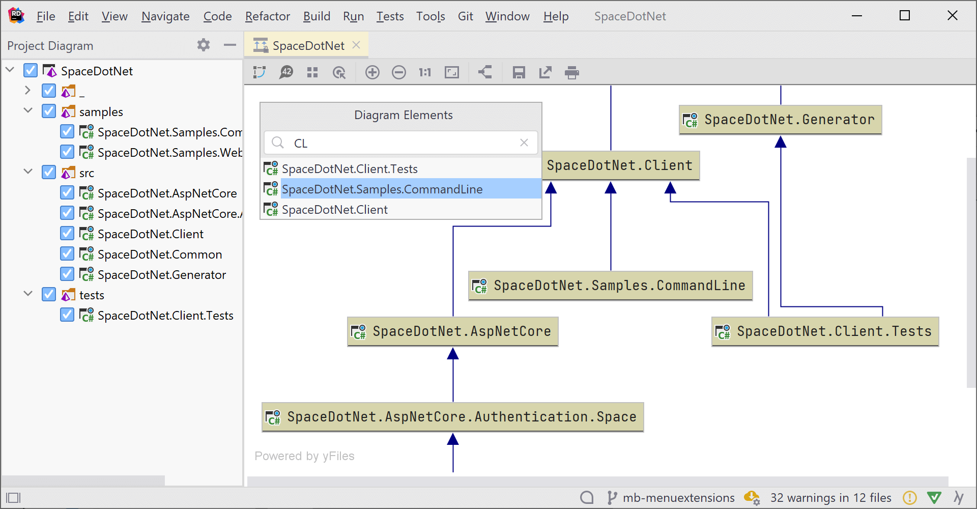
 Project Dependency Diagrams Come To Rider 2020 3 The Net Tools Blog
 Pin On Wiring Diagram
 Pin On Paid Courses And Books For Free
 Multi Level Layer Diagrams Templates Powerpoint Design Diagram
 Project Dependency Diagrams Come To Rider 2020 3 The Net Tools Blog
 Pin On Diagrams
 Multi Level Layer Diagrams Templates Powerpoint Design Diagram
 Pin On Diagrams
 Pin On Windows 10 Product Key
 Data Dissemination Diagrams
 Pin On Diagrams
 Venn Diagrams Representing The Fd Sets And Their Intersections In Download Scientific Diagram