Xt x 1 t. While being charged this type of battery can reach for a duration of one hour a voltage of 34VDC.
 Pin On Document
Add one to the result.

Original input output diagram and the description. The output when you triple the input and subtract 4. Mitra cwlineenthuedutw 03-5731152 8-1 Block Diagram Representation The convolution sum description of an LTI discrete-time system can in principle be used to implement the system Here the inputHere the input-output relation involves a finite sum ofoutput relation involves a finite sum of. Input and output are the fundamental building blocks of a process used to describe a software program.
The outputs are turned on or off at the end of every PLC Scan. The parallel input-output port chip 8255 is also called as programmable peripheral input- output port. Pin7 is the positive voltage supply terminal and Pin4 is the negative voltage supply terminal.
A coil light and motor. Original PowerPoint slides prepared by S. The UPS will still charge battery under this mode.
Inputsoutputs that have a normal operating voltage of 30VDC maximum. 20082012 The Input-Output IPO Model is a functional graph that identifies the inputs outputs and required processing tasks required to transform inputs into outputs. N states state vector Xt m inputs ut and l outputs yt The state and output equations can be written as.
The above diagram has three outputs. The IC draws in power from these pins. 50 Hz or 60 Hz.
What is input and output in a flowchart. The volume of a cube v given its edge length s Write an equation for each description that expresses the output as a function of the input. Name the independent and dependent variables of each equation.
Subtract 78 from the result to get the output. Manual System Input Process Creation of the present System. 15K20K Rear Panel Diagram 5 15KL20KL Input.
Input Devices are the electronic parts of the Computer System used to input the users data or information into computers for the output results. Page 8 Diagram 4. 03012021 An IPO Input-Process-Output Diagram is a very high-level diagram used for systems analysis that visually describes business processes with the description of each component in word.
Multiply the result by 11. 3 11 not connected 1Y 6 data output GND 7 ground 0 V 2Y 8 data output 2A 2B 2C 2D 9 10 12 13 data input VCC 14 supply voltage 1 Input Output nA nB nC nD nY L XXXL XL XXL XXL XL XXXL L HHHHH In accordance with the Absolute Maximum Rating System IEC 60134. You will notice that when the Ladder output turns on the corresponding output card bit LED turns on.
LCD display Battery mode Description When the input voltage is beyond the acceptable range or. It can be defined as an electro-mechanical device that allows a user to input the data into a computer by usually typing on a keyboard or by clicking a mouse by which we can input data into the computer. Voltage 34VDC for up to one hour every 24 hours.
ABCD are constant matrices A is an nxn system dynamics matrix B is an nxm input matrix C is an lxn matrix relating states to outputs D is an lxm matrix relating inputs to outputs. It has 24 inputoutput lines which may be individually programmed in two groups of twelve lines each or three groups of eight lines. Please keep the original package in a safe place for future use.
Why does this work. Symbol Pin Description 1A 1B 1C 1D 1 2 4 5 data input nc. The model is sometimes configured to include any storage that might happen in the process as well.
For this reason all inputoutput modules with an operating voltage of 24VDC can withstand this. Can you describe a simpler way to describe this rule. The Ladder outputs Y0 Y1 and Y2 control the outputs respectfully.
The PLC logic is solved. . The inputs represent the flow of data and materials into the process from the outside.
Choose a 3-digit number as an input and apply the following rule to it one step at a time. For example the input could be provided by a user like at an ATM machine or in a form online or it could data provided by an instrument like a temperature read. 01042017 For that possible completing the research el born area will advice the readers the way the existing computer works and just how the proponent can further improve it.
The program will have code to interpret the input and generate an output. Find the output when the input is 5 for each equation. Subtract 5 from the result.
10K10KL InputOutput Terminal Diagram 3. 4 Pin Diagram of IC741 Op-amp Pin Description. This then will energize the output hardwired to the device.
This is the output pin for the IC. With this an entire input Process Output diagram continues to be organized. The voltage at this pin depends on the input.
The Intels 8255 is designed for use with Intels 8-bit 16-bit and higher capability microprocessors. Multiply the result by 13. The voltage between these two pins lies between 5V and 18V.
Multiply your number by 7.
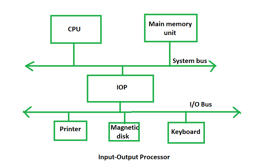 Introduction Of Input Output Processor Geeksforgeeks
 Pin On Circuit Diagram
 Pin On Diagrams
 Pin On Gby
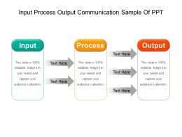 Input Process Output Workflow Powerpoint Templates Powerpoint Templates Designs Ppt Slide Examples Presentation Outline
 Pin On Diagrams
Dual Power Dc Supply 15v Power Supply Circuit Circuit Diagram Circuit
 Pin On Architecture
 Input Process Output I P O Framework For Crowdsourcing Download Scientific Diagram
 Input Output Devices Interactive Circles Output Device School Computer Lab Design Techie Teacher
 Inputs Processes Outputs Outcomes Download Scientific Diagram
 Pin On Computer Science
 Pin On Algebra
 Pin On What Is A Computer